



 English
 中文简体
中文简体 русский
 Español
 عربى
عربىCat:American-Style Box Substation
Product Overview: ZGS series combined transformer is a series of products developed according to the needs of urban multi-grid construction and develo...
See DetailsA wind power substation converts the low-voltage, variable-frequency electricity produced by a wind farm into stable, transmission-ready power, then routes it into the regional grid. Without this single facility, the hundreds of megawatts generated across dozens of turbines would never reach a single household or factory. Every wind farm larger than a handful of turbines depends on one, and the design choices made here — voltage class, transformer sizing, switchgear type, redundancy level — determine how much energy actually gets sold rather than lost.
Turbines typically generate at 690V to 1,000V. That voltage is far too low to travel any real distance without massive losses, so each turbine sends its output through a pad-mounted transformer up to a medium-voltage collector line, usually 33kV or 34.5kV. Dozens of these collector circuits converge at the wind power substation, where a main power transformer steps the voltage up again — commonly to 132kV, 220kV, or 400kV depending on the distance to the interconnection point and the capacity of the local grid.
Inside the substation, three functions happen simultaneously: voltage transformation, protection (isolating faults before they cascade into the grid), and metering/communication (reporting real-time output to the grid operator). A 300MW wind farm, for example, might route power through a single 300MVA main transformer, or split the load across two 150MVA units for redundancy — a decision with real financial consequences discussed further below.
On paper, both facilities step voltage up or down and protect the network. In practice, the operating conditions are different enough that equipment specifications diverge sharply.
| Factor | Wind Power Substation | Conventional Grid Substation |
| Power flow direction | Predominantly one-way, generation to grid | Bi-directional, load-following |
| Load profile | Highly variable, tied to wind speed | Relatively predictable, cyclical by time of day |
| Harmonic content | Higher, from power electronic converters in turbines | Lower, mostly linear loads |
| Transformer duty cycle | Frequent partial-load operation, thermal cycling | Steadier loading, fewer rapid swings |
| Reactive power needs | Requires active compensation (STATCOM, SVC) for grid codes | Generally passive capacitor banks suffice |
| Site environment | Remote, often coastal or elevated, harsher weather exposure | Frequently urban or near existing infrastructure |
The variable, converter-driven nature of wind generation is the biggest engineering difference. Grid codes in most markets now require wind farms to ride through voltage dips and supply reactive power on demand, so the substation must include dynamic compensation equipment that a standard distribution substation would never need.
Location changes almost every design assumption. An onshore facility sits on a concrete pad with road access for maintenance crews; an offshore substation sits on a fixed jacket or floating platform, often 20 to 80 kilometers from shore, and every kilogram of equipment adds to the platform's structural cost.
| Aspect | Onshore Substation | Offshore Substation |
| Typical capacity handled | 50MW to 500MW | 300MW to 1,200MW+ |
| Switchgear type | Often AIS to reduce cost | Almost always GIS to minimize platform footprint |
| Access for maintenance | Road access, routine inspection | Vessel or helicopter access, weather-dependent |
| Corrosion protection | Standard coatings | Marine-grade coatings, cathodic protection, sealed enclosures |
| Redundancy design | Single transformer common on smaller farms | N+1 transformer configuration is near-standard practice |
| Approximate capital cost premium | Baseline | 2.5x to 4x per equivalent MVA, driven by platform and marine installation costs |
Offshore substations also often include High Voltage Direct Current (HVDC) converter equipment when the distance to shore exceeds roughly 80–100 kilometers, since AC transmission losses become uneconomical past that range. An HVDC converter station adds significant cost but can cut transmission losses by more than half over long subsea cable runs compared to AC alternatives.
Choosing the right voltage class is a balance between transmission efficiency and equipment cost. A wind farm exporting 100MW over 10 kilometers might use 132kV comfortably. The same 100MW exported over 60 kilometers often justifies 220kV or higher, because higher voltage cuts current for the same power, which shrinks conductor size and I²R losses.
Transformer sizing typically includes a margin above nameplate capacity — commonly 10% to 15% — to account for future turbine repowering or capacity additions. Splitting capacity across two transformers instead of one increases upfront cost by roughly 15% to 20% but allows the farm to keep exporting at reduced capacity if one unit needs unplanned maintenance, rather than shutting down entirely.
For an asset that may operate for 25 years, availability is money. A single unplanned transformer outage on a 200MW farm can cost tens of thousands of dollars per day in lost generation revenue, depending on local power prices. This is why many developers now specify:
Industry data generally shows that substations with online condition monitoring reduce unplanned outage duration by 30% to 50% compared to those relying solely on scheduled inspections, because problems get identified and scheduled for repair before they force an emergency shutdown.
Anyone evaluating a wind power substation project — whether a developer, an EPC contractor, or an asset owner — tends to weigh the same handful of variables when comparing bids:
Substation siting affects permitting timelines as much as turbine placement does. Noise from transformer cooling fans, visual impact in sensitive landscapes, and proximity to wetlands or protected habitats are common review points. Underground cabling from the substation to the point of interconnection is sometimes required near residential areas, which can add 15% to 30% to that portion of project cost but significantly shortens the permitting process in contested locations.
Most wind power substations step collector voltage up to 132kV, 220kV, or 400kV, depending on the distance to the interconnection point and the capacity of the surrounding transmission network. Larger farms exporting power over long distances generally use higher voltage classes to reduce transmission losses.
A typical onshore project takes 12 to 18 months from design to energization, though main transformer lead times of 18 to 24 months are increasingly the limiting factor. Offshore substations often take longer due to platform fabrication and marine installation logistics.
Grid operators require wind farms to maintain voltage within a set band and ride through short disturbances without disconnecting. Because wind turbines use power electronic converters rather than traditional synchronous generators, a wind power substation needs active devices like STATCOMs or SVCs to meet these grid code requirements.
A collector substation gathers medium-voltage output from multiple turbine strings within the wind farm. The main wind power substation then steps that collected power up to transmission voltage for delivery to the grid. On smaller farms, both functions can be combined into a single facility.
Many wind power substations use two smaller transformers instead of one large unit, or maintain a spare unit on standby, so the farm can continue exporting at reduced capacity during maintenance or an unplanned outage rather than shutting down entirely.
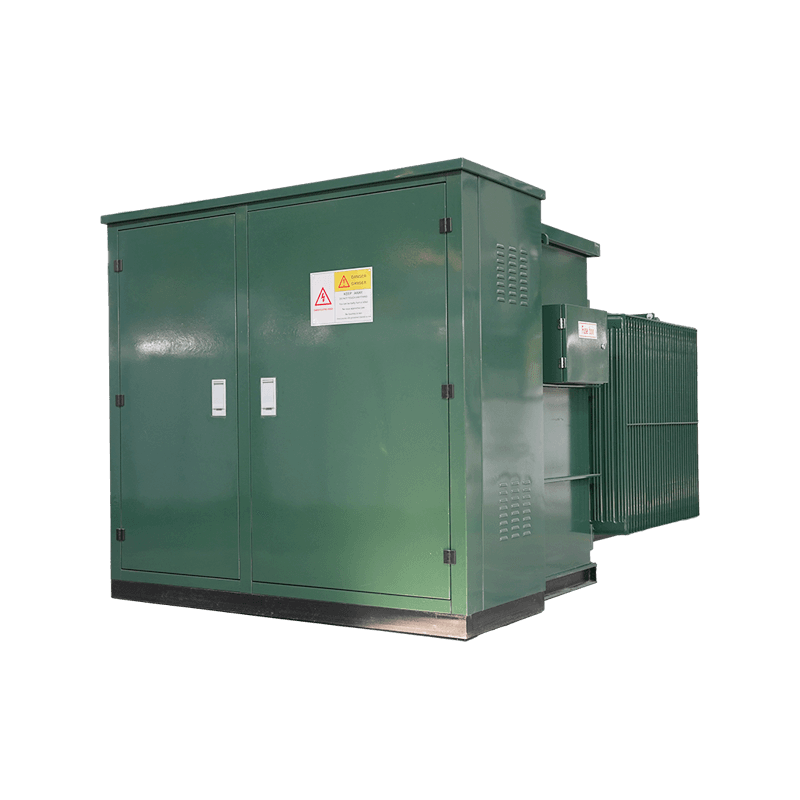
Product Overview: ZGS series combined transformer is a series of products developed according to the needs of urban multi-grid construction and develo...
See Details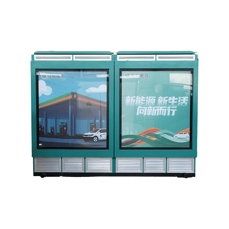
Product overview:Semi-buried box substation (barrel weight semi-buried box transformer) is a new generation of box-type transformer newly developed on...
See Details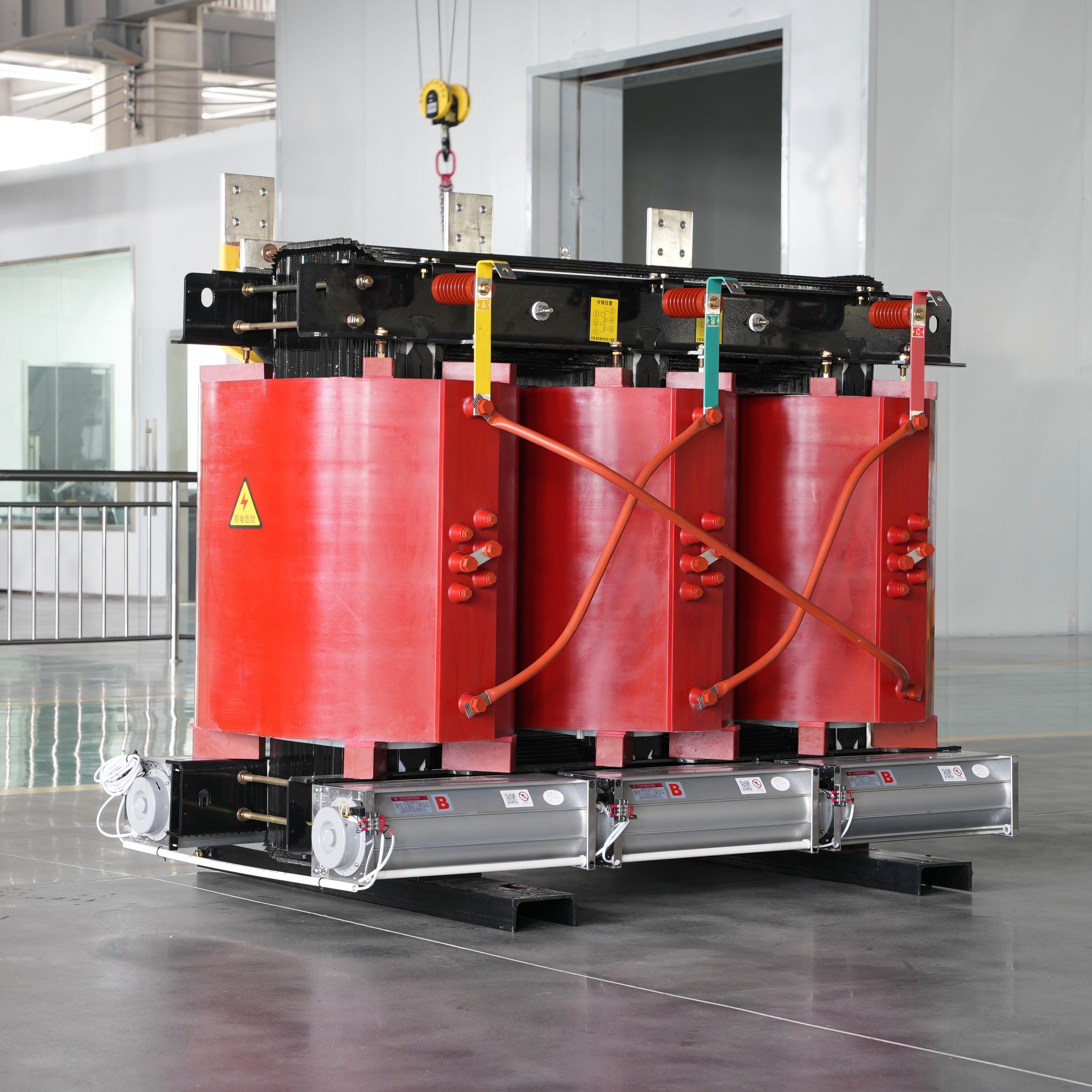
SC (B) series products are epoxy-cast non-excited voltage regulating dry transformers; This type is made of F-grade epoxy resin mixture with filler, a...
See Details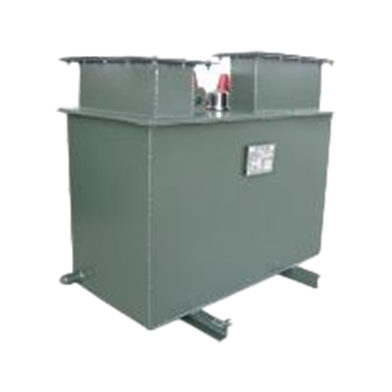
Product Overview: Underground transformer: a distribution transformer or combined transformer that can be installed in a pit. It is generally installe...
See Details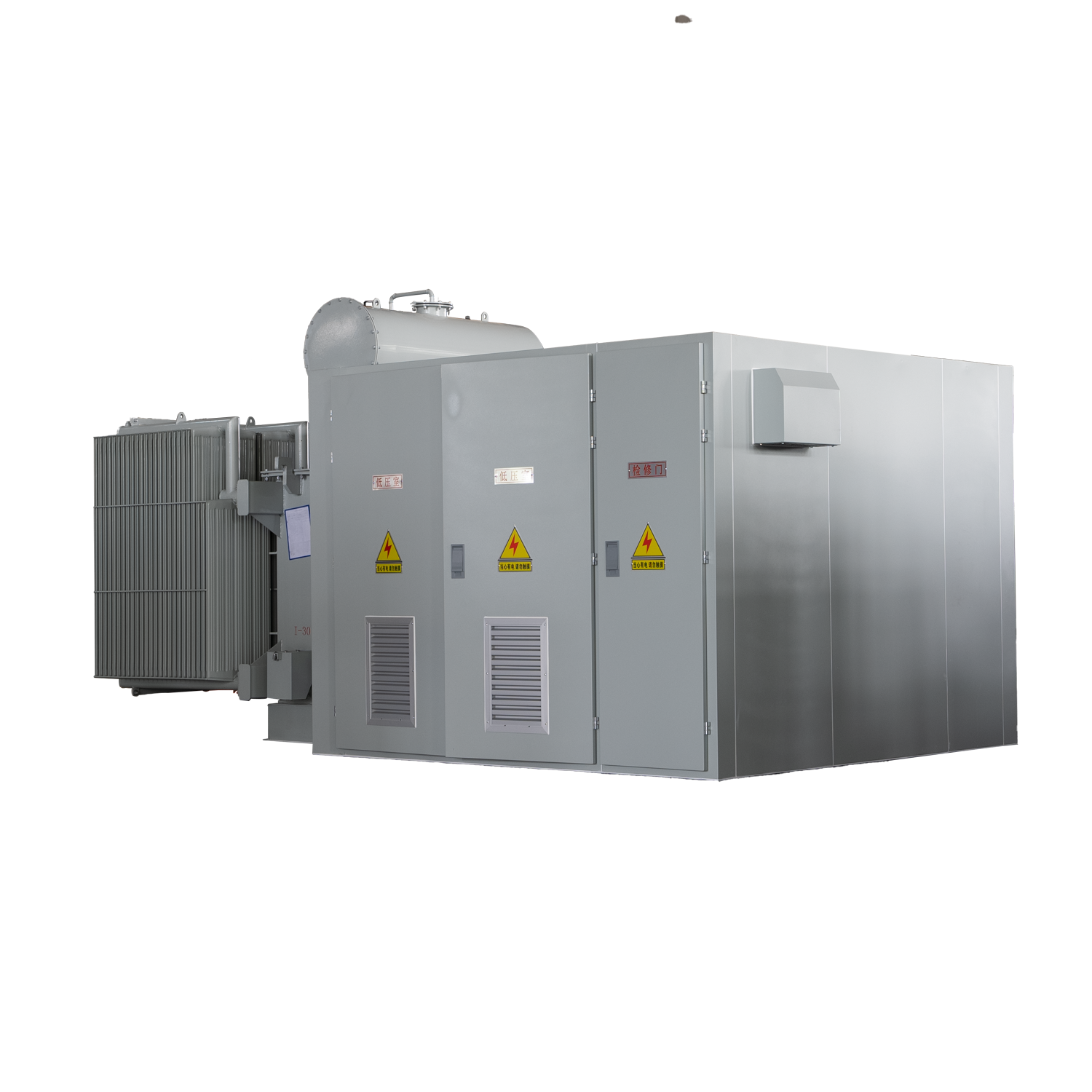
Product overview: Wind combined transformer series products for our company specially designed and developed for wind power generation products, wind ...
See Details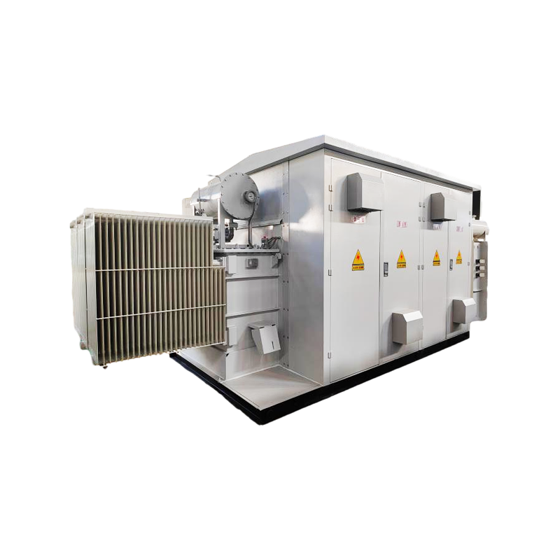
An energy storage box substation is a substation that integrates a traditional substation and energy storage system in a box. It is mainly composed of...
See DetailsRequest for a call today




Contact Us